Center thickness & air gap measurement
The important opto-geometric parameters of any optical system include the (center) thickness of the elements installed and the air gaps between them. This is true for the visible as well as for the infrared spectral range. With short coherence interferometers from TRIOPTICS you can measure these properties in a non-contact way in production and development and thus positively influence the imaging quality of your optics.
Applications

Center thickness measurement
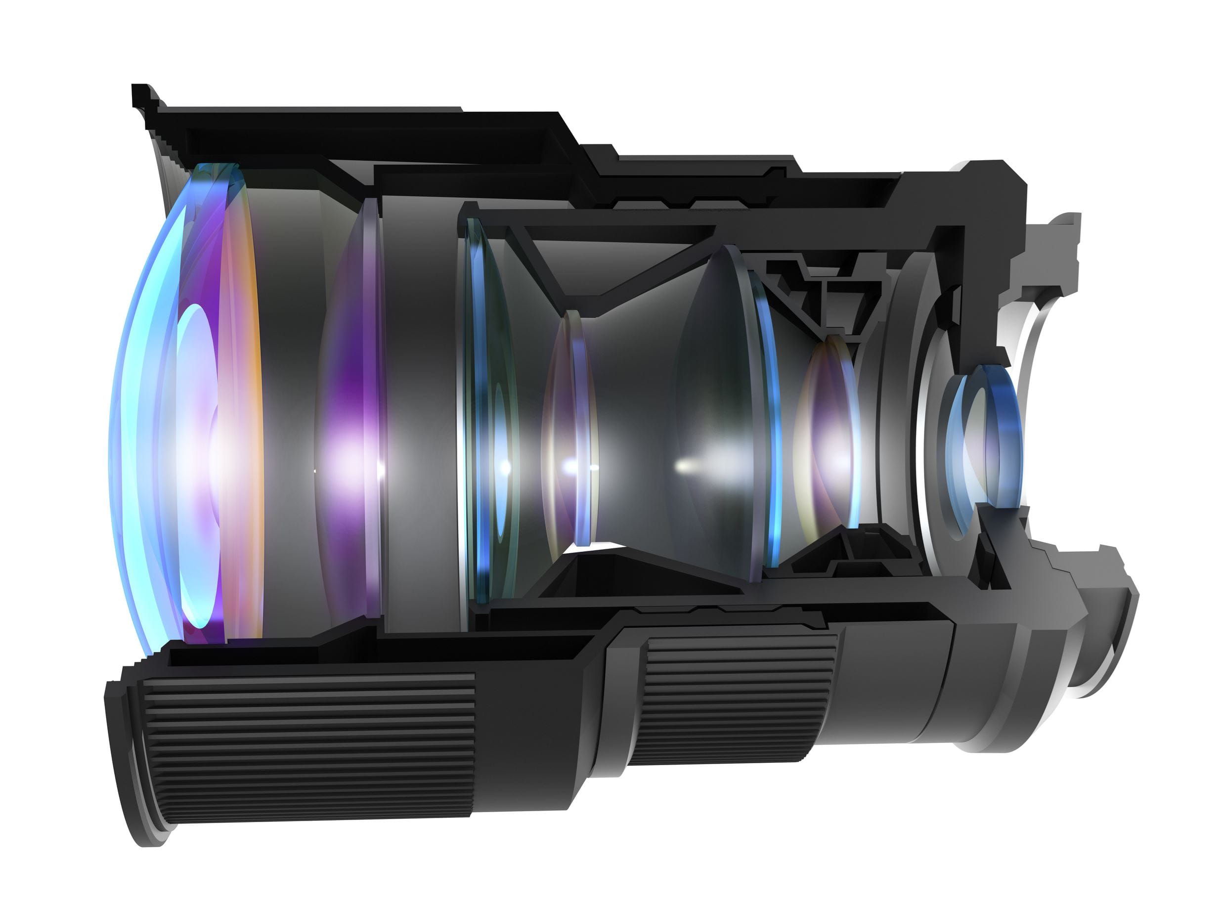
The center thickness of the individual lens elements must be determined both for individual lenses and in the assembled lens. Our solutions allow this to be done in the development process, during production with OptiSurf® LTM when the lens is still blocked, as well as in the final quality control using OptiSurf® – then also in combination with a centration measurement.

Air gap measurement
Distance is also important! More specifically, the distance between each lens element within an objective lens. This can be determined parallel to the center thickness using OptiSurf® or combined with a centration testing device via OptiCentric® 3D.

Testing geometrical properties of AR waveguide stacks and plano-optical elements with OptiSurf® PRO AR
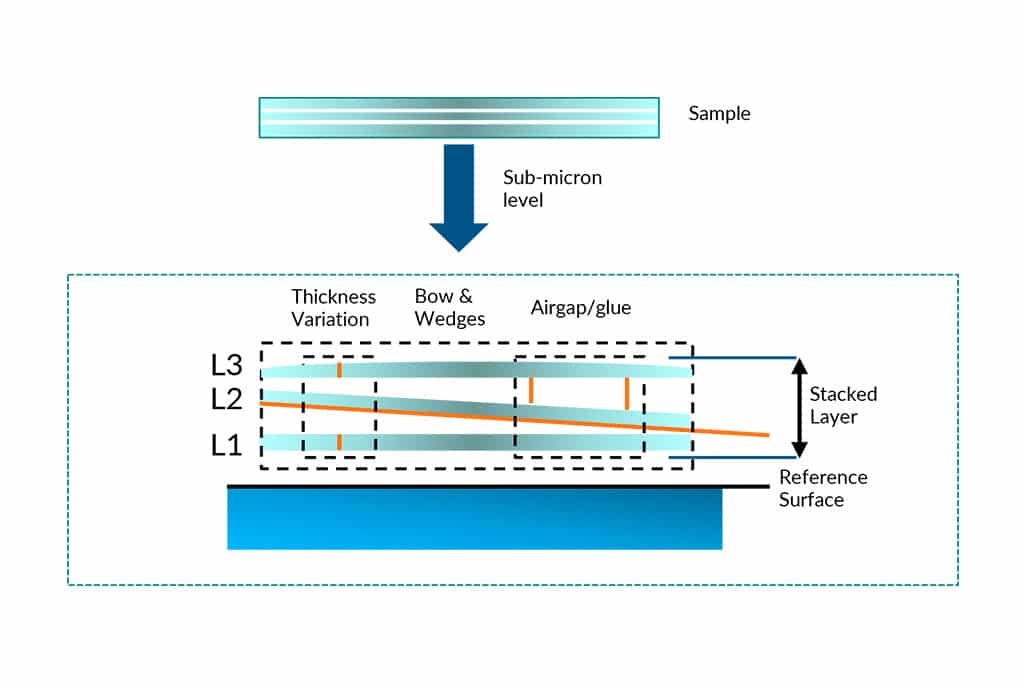
We offer solutions for the production, development or quality control of stacked waveguides or optical elements. This includes the measurement of factors that influence the image quality, such as uneven thickness of the sample layers, air gaps and glue between the stacked layers, tilt of the layers as well as internal bow of the stacked layers.
Coffee Break
No time for long explanation videos?
Get the essentials on a wide range of technology topics during a coffee break.
Just measure it
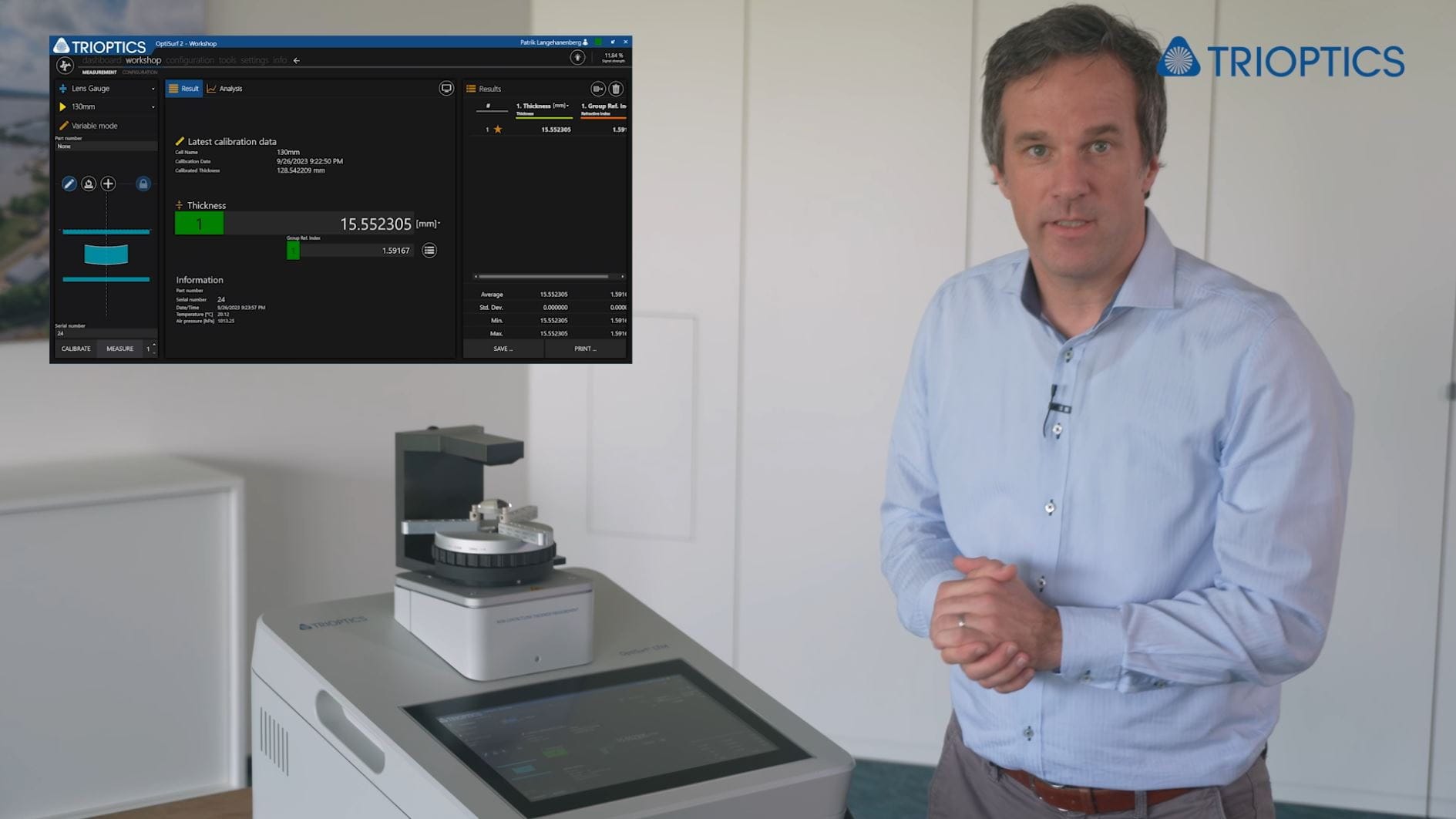
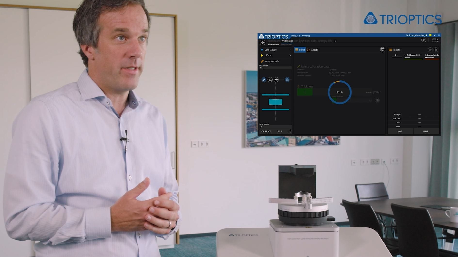
Non-contact center thickness measurement

Lens material uncovered
Measure the refractive index of a finished lens
Knowledge base

The main measurement applications of the OptiSurf® PRO AR are the following:
- Non-destructive characterization of the geometrical properties of single AR waveguides or plano-optical elements: measurement of gravitational sag, 2D thickness profile, total thickness variation, 1D and 2D wafer bow, etc.
- Non-destructive characterization of the geometrical properties of stacked AR waveguides consisting of two or more waveguides with air gaps in between: 2D thickness profile, total thickness variation, 1D and 2D wafer bow, etc. for the individual waveguides as well as 2D tilt and distance (air gap thickness) between waveguides.
Factors affecting image quality:
- Uneven thickness of layer/sample
- Airgap/glue between the stacked layer
- Tilt of layers
- Internal bow of stacked layers
Our Newsletter – Your advantage in knowledge
Be one of the first to experience our product novelties and innovative application possibilities.